


valutazioni - 0, GPA: 4
(

 )
)
|
Foto e specifiche Makita 6827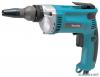 |


Facilità d'uso
hertz .../min................revolutions or reciprocation per minute ................ alternating current FUNCTIONAL DESCRIPTION FUNCTIONAL DESCRIPTION 12 3 4 1. Pointer 2. Locator 3. Front cap 4. Adjusting ring 002622 1mm (3/64") 002623 1mm (3/64") CAUTION: • Always be sure that the tool is switched off and unplugged before adjusting or checking function on the tool. Depth adjustment When you wish to drive self drilling screws, etc., adjust the depth as follows. Turn the locator to adjust the depth. Initially, adjust the locator to create a distance of approximately 1 mm (3/64”) from the tip of the front cap (which works in conjunction with the locator) to the base of the screw head. One full turn of the locator equals 1 mm (3/64”) change in depth. After adjusting the locator, turn the adjusting ring so that the 6” mark is aligned with the pointer on the gear housing. Drive a trial screw into your material or a piece of duplicate material. If the depth is not suitable for the screw, continue adjusting until the proper depth setting is obtained. 1 2 1 2 Switch trigger 2. Lock button 002628 Switch action CAUTION: • Before plugging in the tool, always check to see that the switch trigger actuates properly and returns to the “OFF” position when released. To start the tool, simply pull the switch trigger. Tool speed is increased by increasing pressure on the switch trigger. Release the switch trigger to stop. For continuous operation, pull the switch trigger and then push in the lock button. To stop the tool from the locked position, pull the switch trigger fully, then release it. NOTE: • Even with the switch on and motor running, the bit will not rotate until you fit the point of the bit in the screw head and apply forward pressure to engage the clutch. 002635 1. Reversing switch lever A B 1 Reversing switch action This tool has a reversing switch to change the direction of rotation. Move the reversing switch lever to the position (A side) for clockwise rotation or the position (B side) for counterclockwise rotation. CAUTION: • Always check the direction of rotation before operation. • Use the reversing switch only after the tool comes to a complete stop. Changing the direction of rotation before the tool stops may damage the tool. 1 23 1 23 Locator 2. Adjusting ring 3. Pointer A 1. Hook 002642 Adjusting the fastening torque When you wish to drive machine screws, wood screws, hex bolts, etc. with the predetermined torque, adjust the fastening torque as follows. The fastening torque may be adjusted by turning the adjusting ring. Before turning the adjusting ring, turn the locator in the direction of the arrow as far as it will go without forcing. The torque is increased by turning the adjusting ring in the direction of the arrow and decreased by turning it in the opposite direction. Align the number 1 on the adjusting ring with the pointer on the gear housing. Drive a trial screw into your material or a piece of duplicate material. If the fastening torque is not suitable for the screw, continue adjusting until the proper torque is obtained. CAUTION: • The adjusting ring should be turned only within the numbered range. It should not be forced beyond this range. 002646 Hook The hook is convenient for temporarily hanging the tool. 1 When using the hook, pull it out in A direction and then push it in B direction to secure in place. When not using the hook, return it back to its initial position by following the above procedures in reverse. B 002647 ASSEMBLY ASSEMBLY CAUTION: • Always be sure that the tool is switched off and unplugged before carrying out any work on the tool. Installing or removing the bit 002655 To remove the bit, first pull the front cap off and then pull the bit out firmly. To install the bit, insert it into the tool as far as it will go and then replace the front cap. Fit the screw on the point of the bit and place the point of the screw on the surface of the workpiece to be fastened. Apply pressure to the tool and start it. Withdraw the tool as soon as the clutch cuts in. Then release the switch trigger. CAUTION: When fitting the screw onto the point of the bit, be careful not to push in on the screw. If the screw is pushed in, the clutch will engage and the screw will rotate suddenly. This could damage a workpiece or cause an injury. • Make sure that the bit is inserted straight in the screw head, or the screw and/or bit may be damaged. NOTE: • When driving wood screws, predrill pilot holes to make driving easier and to prevent splitting of the workpiece. See the chart. OPERATION • 002675 Nominal diameter Recommended size of of wood screw pilot hole 1/8” 5/64” 9/64” 3/32” 5/32” 7/64” 11/64” 1/8” 3/16” 1/8” 13/64” 9/64” 7/32” 5/32” 15/64” 11/64” 1/4” 11/64” MAINTENANCE MAINTENANCE CAUTION: • Always be sure that the tool is switched off and unplugged before attempting to perform inspection or maintenance. To maintain product SAFETY and RELIABILITY, repairs, carbon brush inspection and replaceme...