


valutazioni - 0, GPA: 0
(
 )
)
|
Foto e specifiche MSI Z87 XPOWER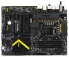 |


Facilità d'uso
• For iPad, JUSB1(red mark) can still charge iPad in S3, S4, S5 state. • We recommend that don’t disconnect the device when you charge it in S1 state. Getting Started 1-28 JUSB3~4: USB 3.0 Expansion Connector The USB 3.0 port is backwards compatible with USB 2.0 devices. It supports data transfer rates up to 5Gbits/s (SuperSpeed). Important 5.USB3_TX_C_DN4.Ground3.USB3_RX_DP2.USB3_RX_DN1.Power10.Ground9.USB2.08.USB2.07.Ground6.USB3_TX_C_DP20.NoPin19.Power18.USB3_RX_DN17.USB3_RX_DP16.Ground15.USB3_TX_C_DN14.USB3_TX_C_DP13.Ground12.USB2.0- + • Note that the VCC and GND pins must be connected correctly to avoid possible damage. • To use a USB 3.0 device, you must connect the device to a USB 3.0 port through an optional USB 3.0 compliant cable. JCI1: Chassis Intrusion Connector This connector connects to the chassis intrusion switch cable. If the computer case is opened, the chassis intrusion mechanism will be activated. The system will record this intrusion and a warning message will flash on screen. To clear the warning, you must enter the BIOS utility and clear the record. 1.Ground Chapter 1-29 Getting Started JAUD1: Front Panel Audio Connector This connector allows you to connect the front audio panel located on your computer case. This connector is compliant with the Intel® Front Panel I/O Connectivity Design Guide. 10.HeadPhoneDetection 6.MICDetection 8.NoPin 4.NC 2.Ground 9.HeadPhoneL 7.SENSE_SEND 5.HeadPhoneR 3.MICR 1.MICL MSATA_1: mSATA Slot The mSATA slot is for mSATA interface solid state drives (SSD). Important The SATA5 port will be unavailable when install a SSD in the mSATA port. Chapter 1 Getting Started 1-30 Voltage Checkpoints These voltage checkpoints are used to measure the current system voltages. A multimeter (not included) will be required to check voltages. FV1: V-Check Connectors To check the voltage, please use the optional voltage checkpoint cables included in the motherboard package. Attach the positive lead of the multimeter to the voltage checkpoint cable and the negative lead to the ground connector. 1 GND CPU_SA CPU_RING CPU_GFX CPU_CORE0 VCC_DDR VCCP 7 Chapter Connector GND (pin 7) CPU_SA (pin 6) CPU_RING (pin 5) CPU_GFX (pin 4) CPU_CORE0 (pin 3) VCC_DDR (pin 2) VCCP (pin1) Description Ground The CPU_SA (CPU System Agent) voltage is the voltage supplied to the integrated memory controller inside the CPU. The CPU Ring is an interface for integrated controllers inside the CPU. The CPU Ring voltage can affect the CPU overclocking performance. The CPU_GFX voltage is the voltage supplied to the integrated graphics processor located on the CPU. CPU core0 voltage. The CPU voltage is the voltage supplied to the CPU core0. Higher overclocks may require higher CPU core0 voltages to maintain stability. Memory voltage. The DDR memory voltage is the voltage supplied to the DDR memory modules on the motherboard. Lower memory timings may require higher voltages to maintain system stability. The CPU VCC input voltage is the CPU power source that is shared with components of the CPU. 1-31 Getting Started V-Check Spots These voltage check spots are for you to measure the voltages. To check the voltage, please attach the positive lead of the multimeter to these spots and the negative lead to any ground spot. Chapter 1 PCH_1P05PCH_1P5CPU_VTTCPU_CORE1CPU_CORE2CPU_CORE3VCCIOA Spot PCH_1P05 PCH_1P5 CPU_VTT CPU_CORE1 CPU_CORE2 CPU_CORE3 VCCIOA Description PCH 1.05V voltage PCH 1.5V voltage CPU VTT voltage CPU core1 voltage CPU core2 voltage CPU core3 voltage IO voltage for CPU VCC Getting Started 1-32 Buttons & Switches The motherboard has numerous on-board buttons to control various functions. This section will explain how to change your motherboard’s functions through the use of these on-board buttons. OC1: OC Genie Button This button is used to automatically overclock the system. Press this button once while the system is off to enable OC Genie. The button will lock remain depressed until it is pushed again to disable OC Genie. On the next boot, the OC Genie utility will automatically overclock the CPU settings to optimal performance values. To disable Chapter OC Genie, power off the system and press the OC Genie button again. The button will depress and the CPU configuration settings will return to normal values. OCGENIEOCGENIEOn Off Important • This motherboard provides two ways to enable OC Genie: press the physical OC Genie button on the motherboard, or click the virtual OC Genie button in BIOS. You can specify how OC Genie to be enabled by using the "OC Genie Function Control" item in BIOS. • Please install DDR3 1333 or faster memory and equip a better heatsink/cooler to use the OC Genie function. • We do not guarantee the OC Genie overclocking range or the damages/risks caused by overclocking behavior. • It is possible to disable the OC Genie function in the BIOS setup. Please refer to the BIOS section of the manual for instructions on how to turn off OC Genie from the BIOS. • The usage of OC ...